

In order to test my low-cost transfemoral rotator prototype (see previous post), my team and I partnered with Mobility India, in Bengaluru, and Jaipur Foot (BMVSS), in Jaipur. Both organizations, founded and based in India, are inspiring NGOs, who strive to provide prostheses to impoverished amputees at little to no cost. We spent three days at each facility, each day testing and getting feedback from a single user. Our six users consisted of men ranging in age from 20 to 79, and in weight from 94 to 183lbs (sans prosthesis). We assessed the functionality of the rotator with a series of clinical tests, comprising of gait analysis, with and without the rotator. Some of these tests included having timed trials of the patient walking, standing up and sitting down, crossing and uncrossing legs, and tying and untying shoe laces.
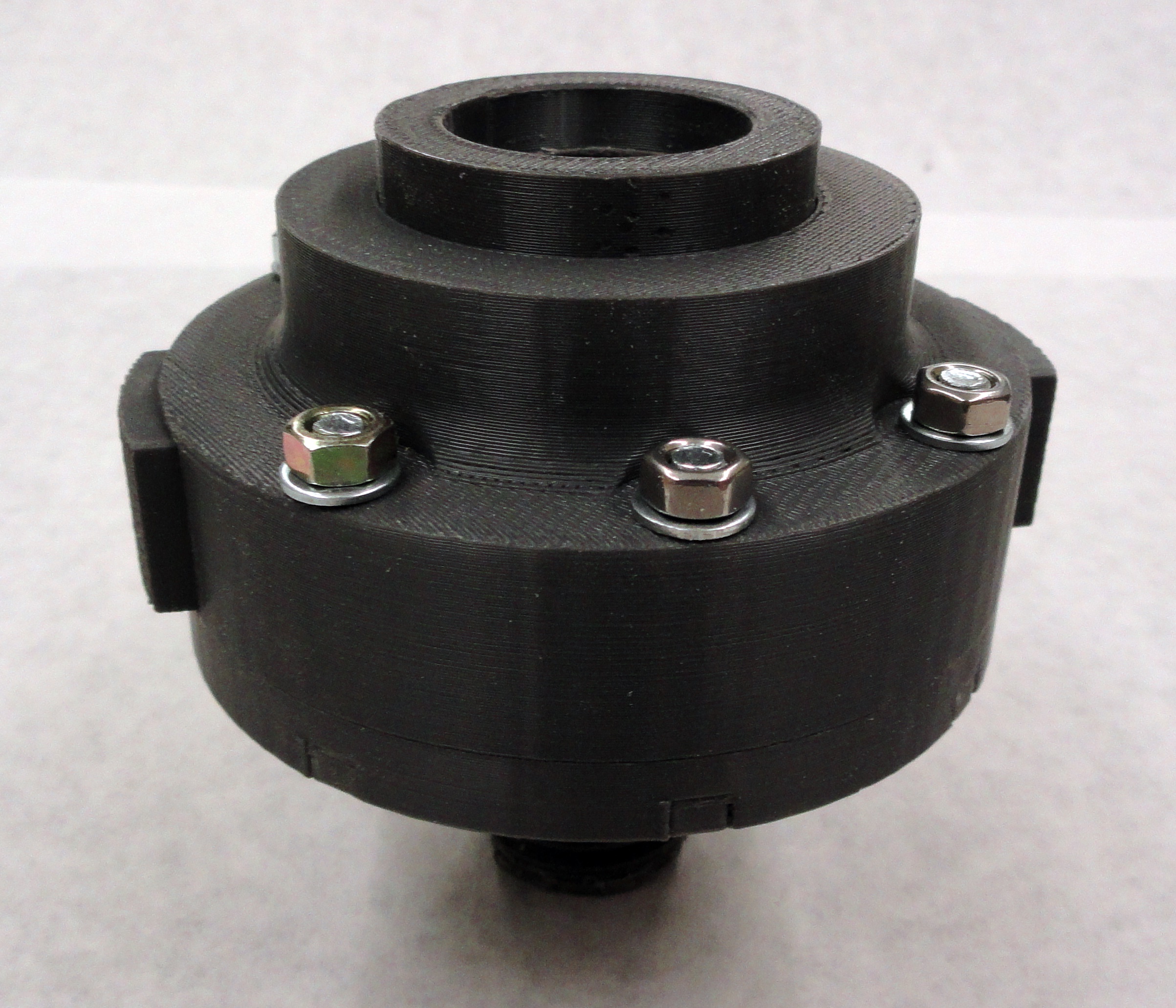
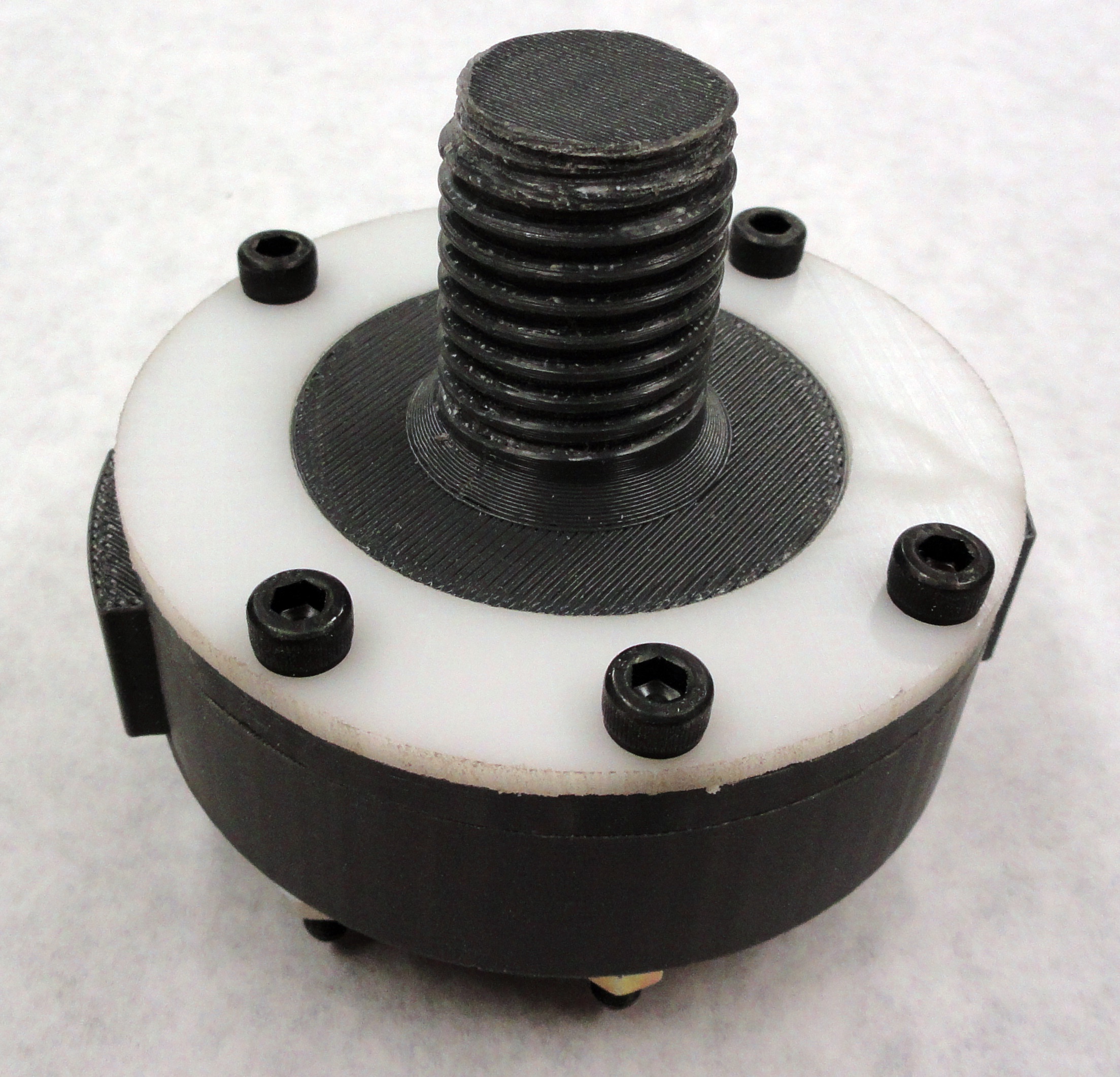
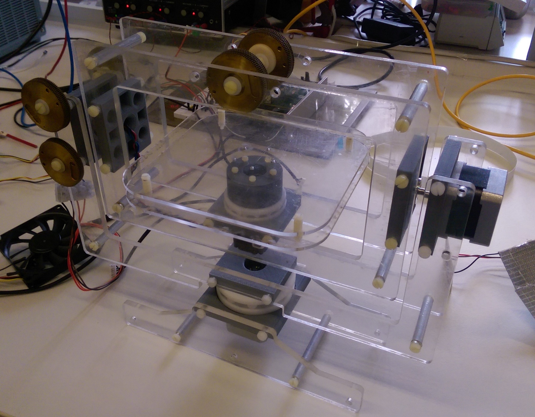
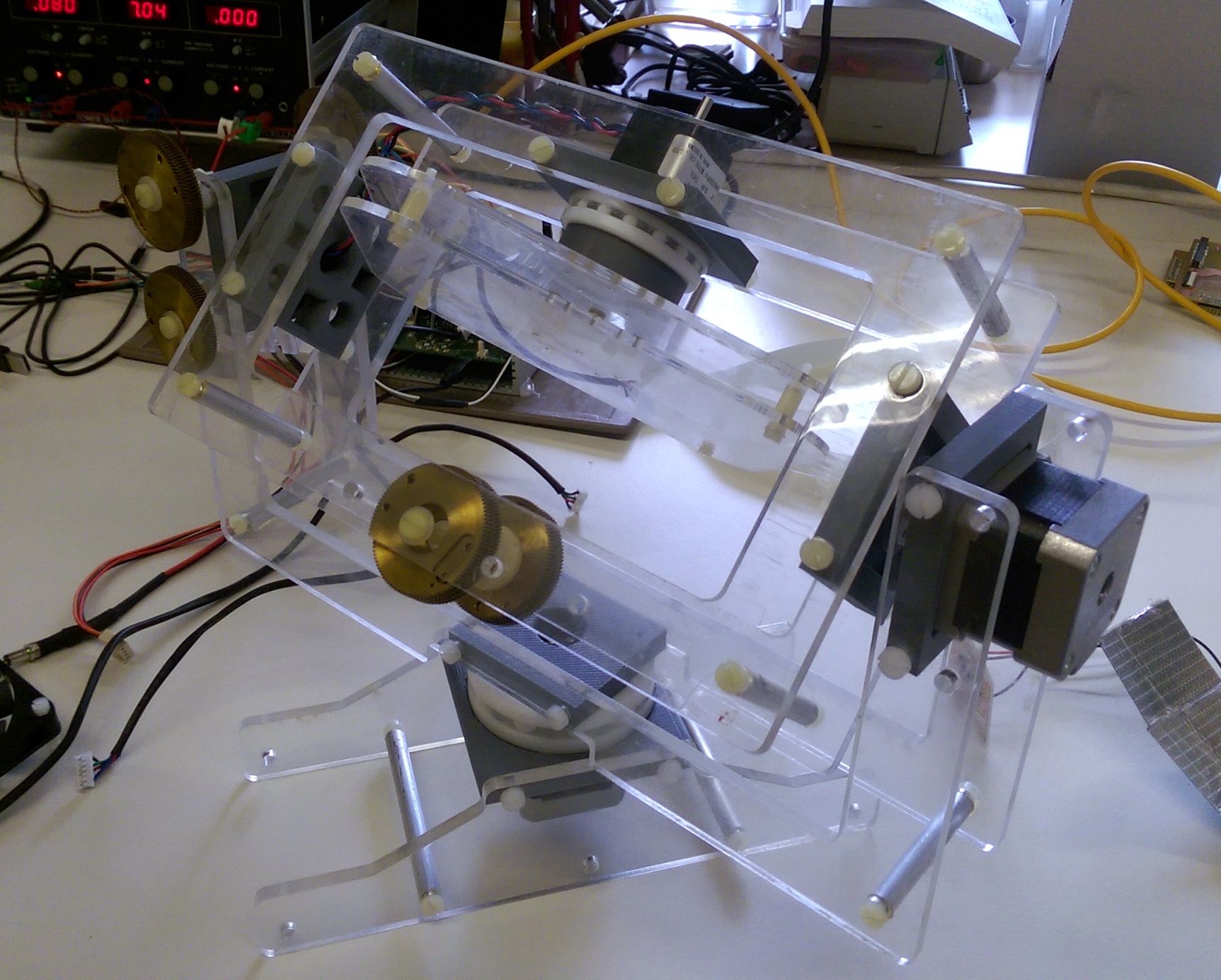
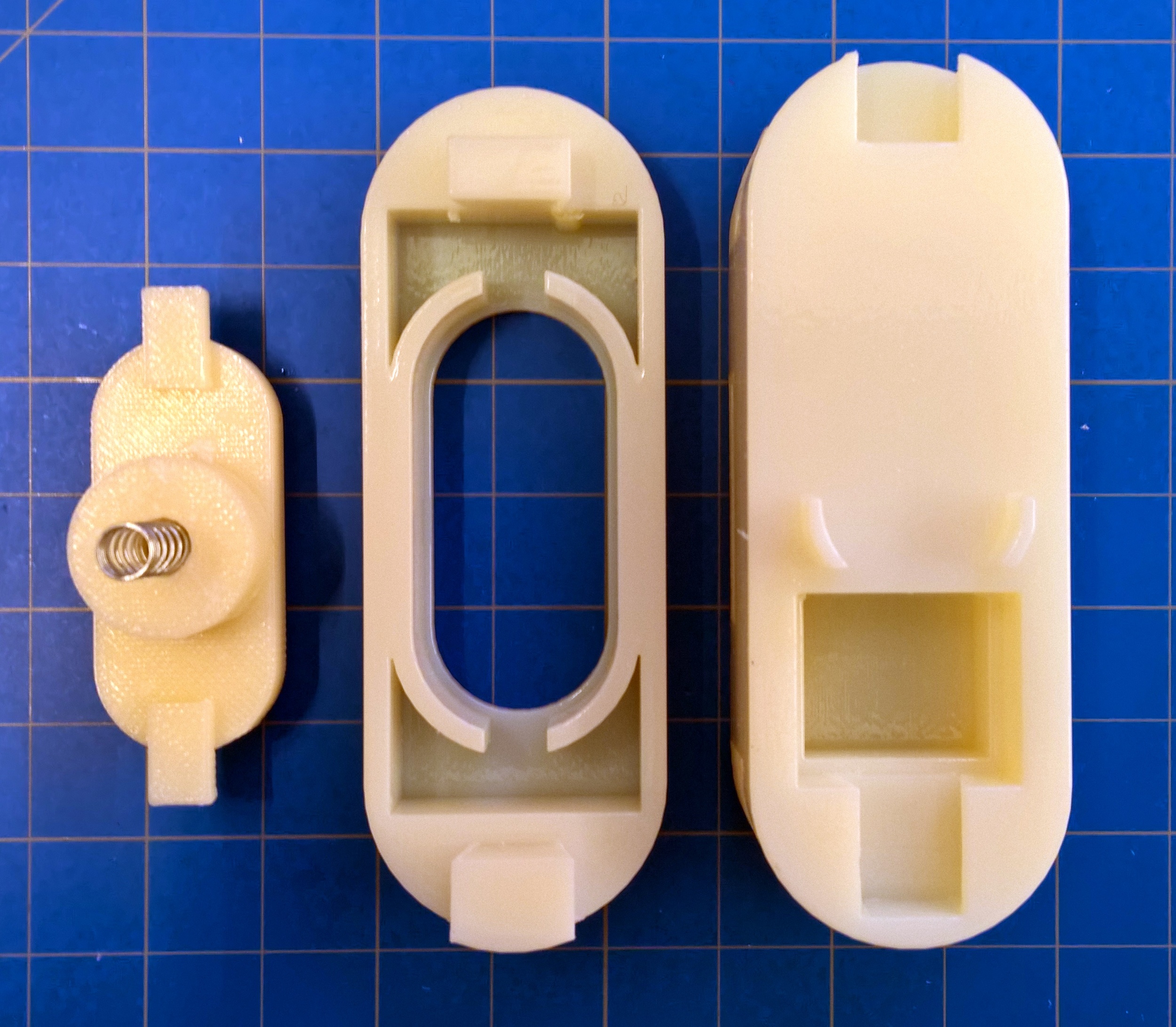
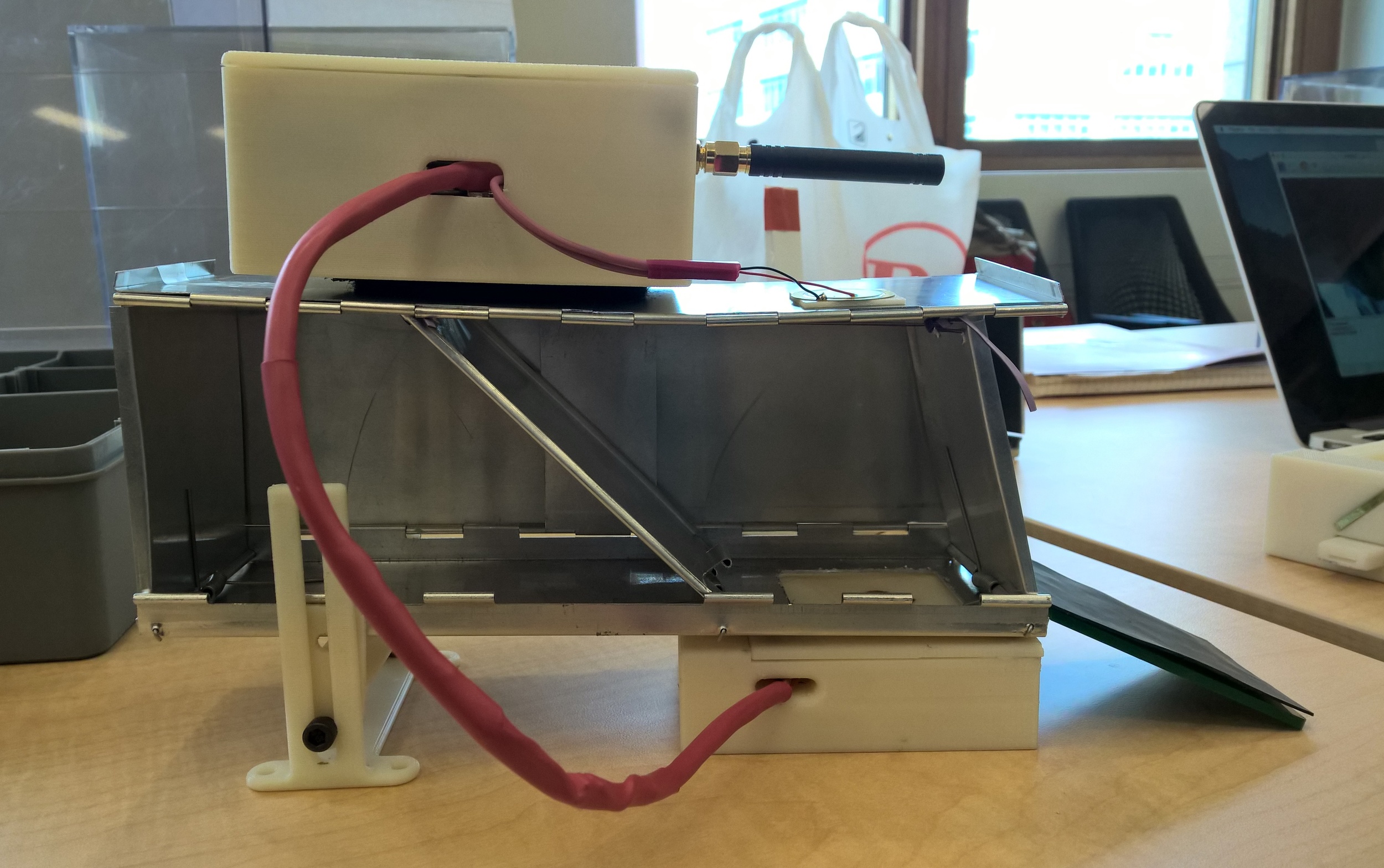
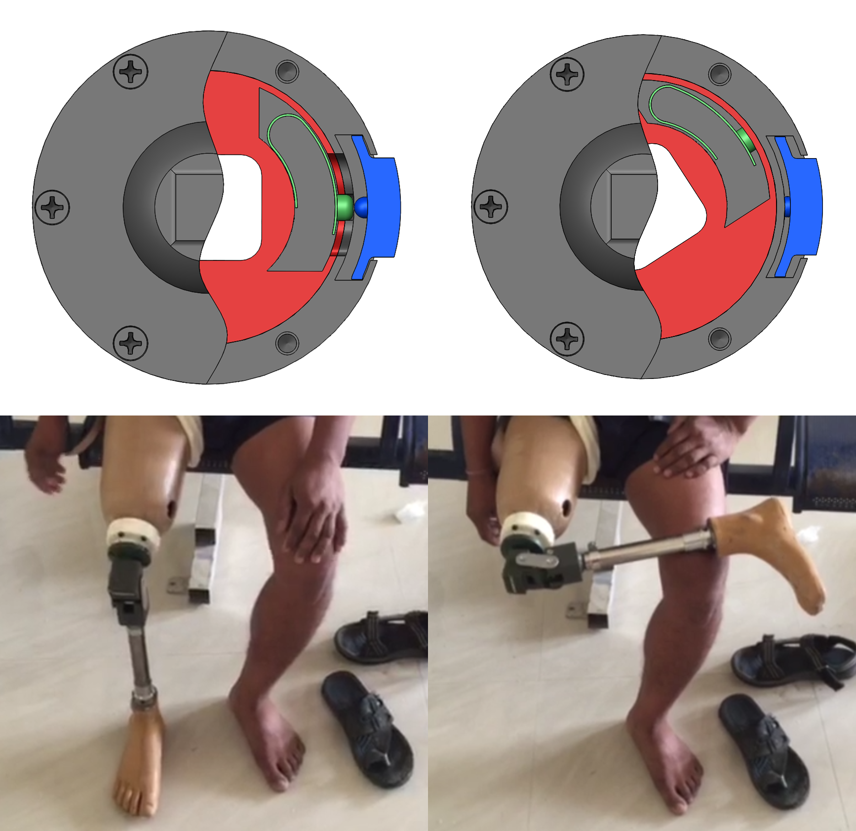
Fig. 2
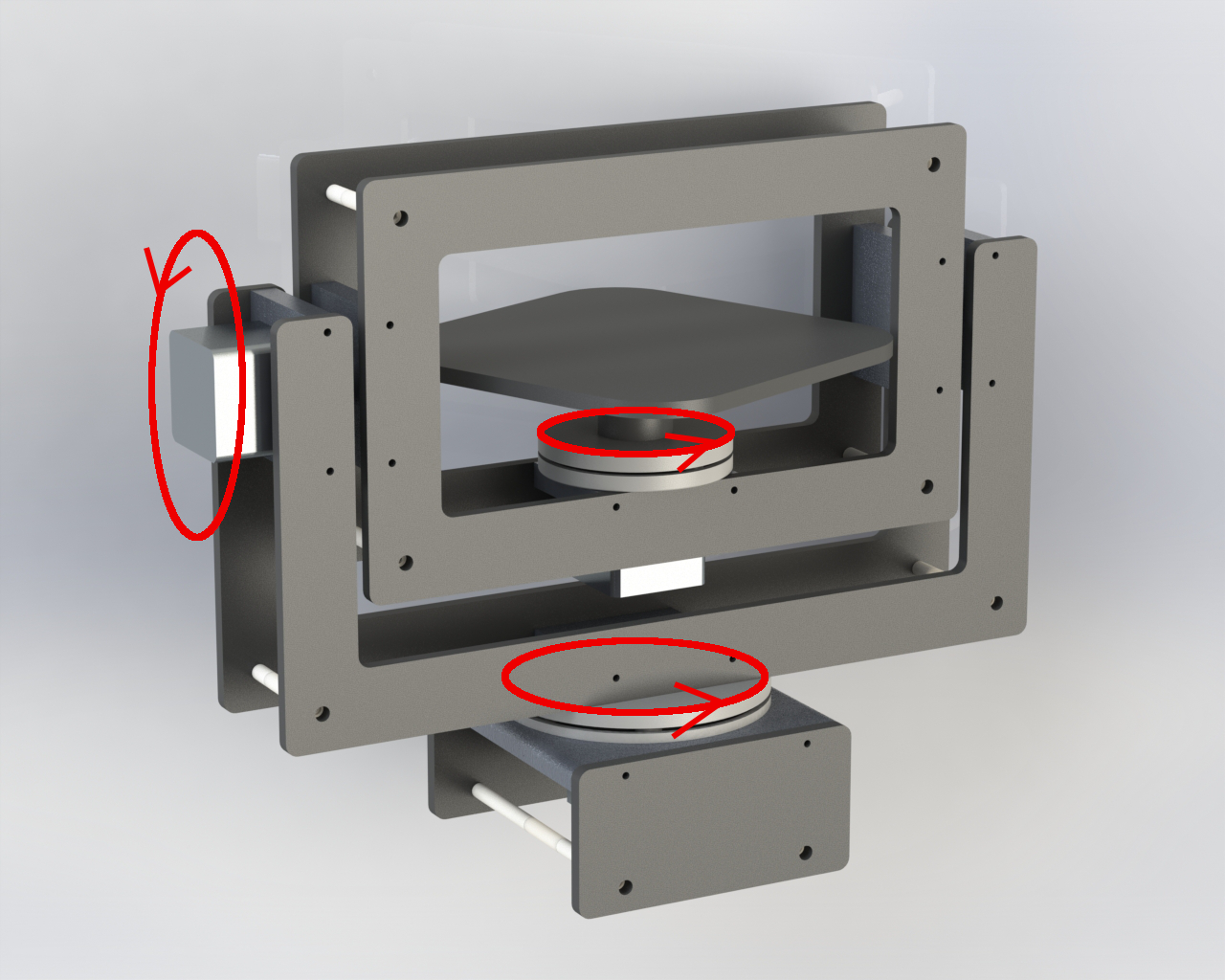
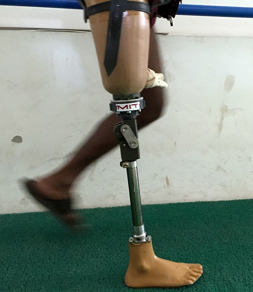
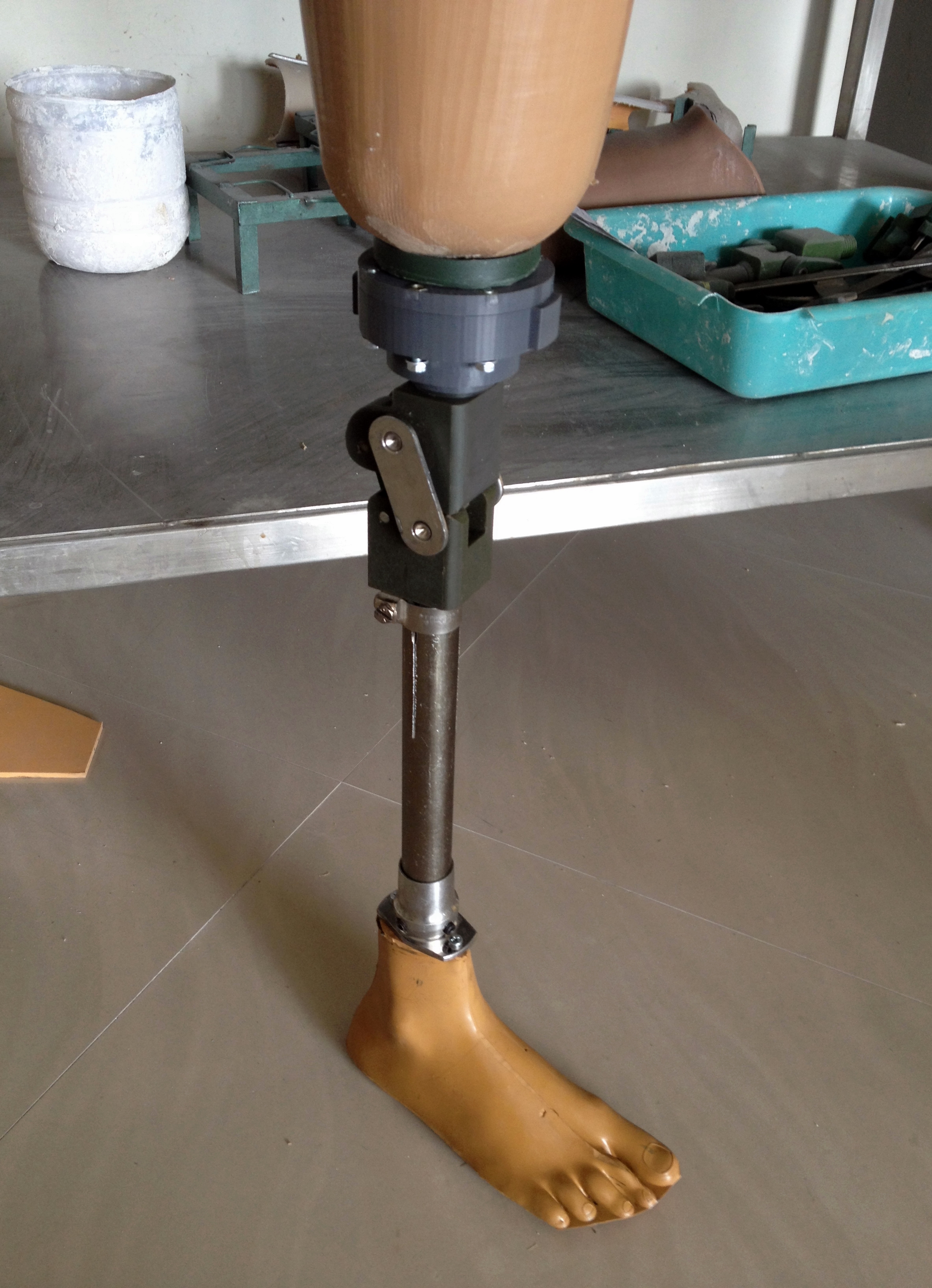
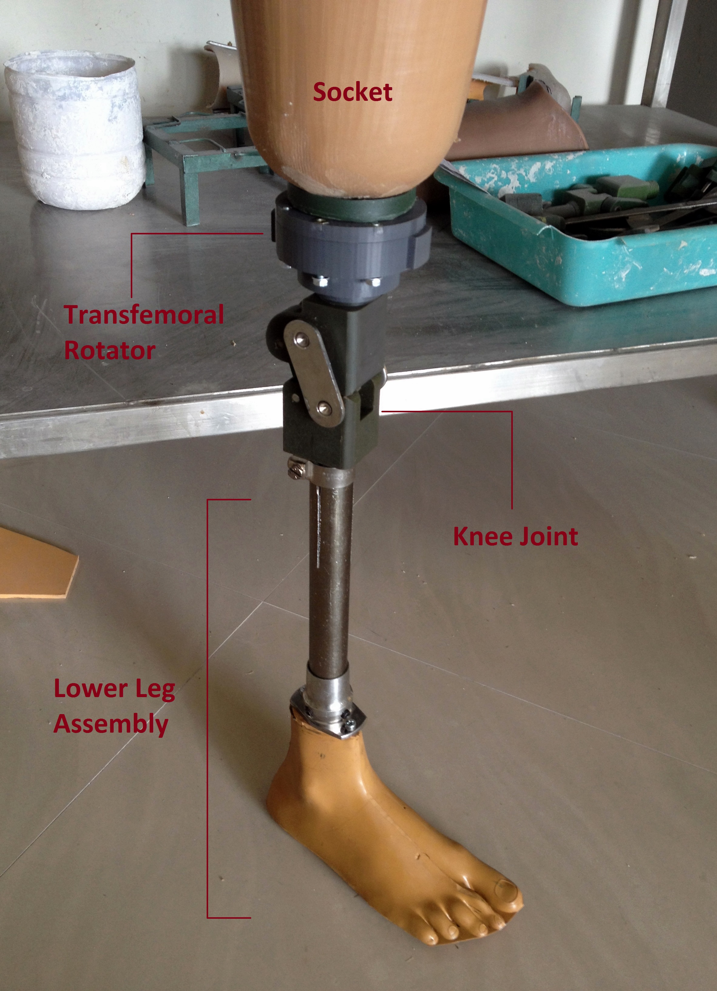
Since Jaipur Foot and Mobility India use different connection methods for their prostheses, a proprietary screw design and a more universal pyramid connector design respectively, I constructed two different prototypes. In figure 2, I used the leftmost prototype for testing at Jaipur Foot and the rightmost prototype for testing at Mobility India. Both prototypes have identical internal mechanisms and are mostly constructed out of printed ABS plastic. Consistent with all transfemoral rotators, the prototype was placed between the socket and knee joint of the prosthesis as shown in figure 3. The only other difference in testing at the two organizations was that at Mobility India, patients used their current socket, knee joint, and lower leg assembly for testing. This meant that the knee joint was somewhat displaced to a lower than normal position. In contrast, at Jaipur Foot, brand new sockets, knee joints, and lower leg assemblies were constructed specifically for the purpose of testing, avoiding displacement of the knee joint. Fortunately, judging from feedback at the two organizations, this difference had little to no impact on the testing results.
Fig. 1
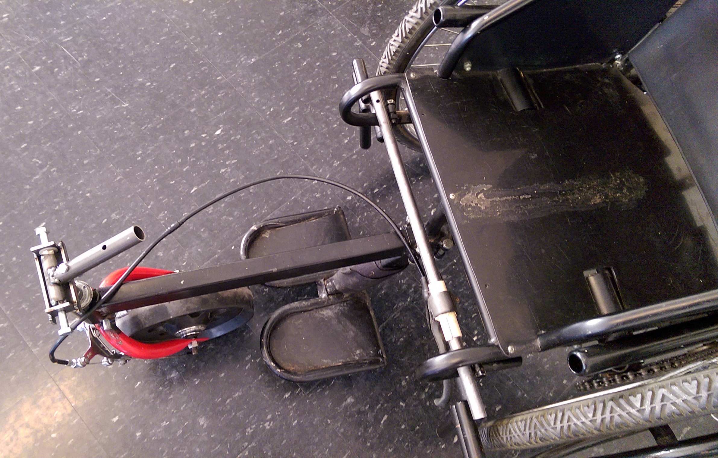
Fig. 3
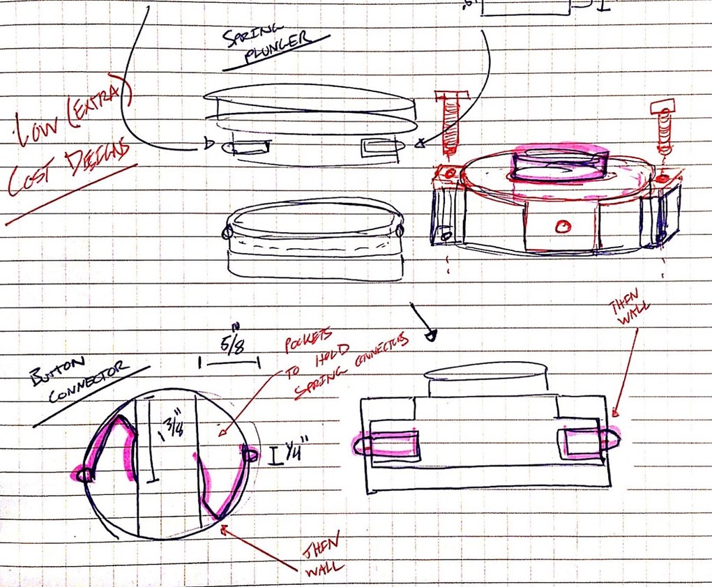
The experience and feedback received at both organizations was reassuringly consistent and positive. Users hardly noticed the added weight of the rotator and appreciated the circumferential size and circular shape. Lacking sharp corners or unnatural straight edges, the rotator was more easily concealed under pants and coverings. Perhaps the most agreed upon critique of the design, however, was the preference to have one, instead of two, unlocking buttons. Older users, and those with smaller hands, found it somewhat difficult to operate both unlocking buttons simultaneously.

Fig. 4
Despite all the data and concrete feedback we received about the design aspects of the rotator, easily the most fulfilling part of testing was getting to see the patients' faces and reactions as they were suddenly able to complete tasks that before existed only as a desire. Costing thousands of dollars in developed countries, transfemoral rotators are a luxury that, until now, was unattainable in the developing world. Simply being able to sit cross-legged, in some cases for the first time in a decade, was life changing for our users. Especially in a culture such as that found in India, sitting cross-legged again can allow much more integrated participation in one's customs and traditions.
Furthermore, the addition of a transfemoral rotator can allow for many activities that may not initially come to mind as being difficult or impossible for an amputee. Above the knee amputees, due to a variety of factors (such as restricted hip rotation in a socket and loss of local muscle structure), are not able to tie their shoes or put on their pants without removing their prosthesis. Below are videos of our patients doing both.
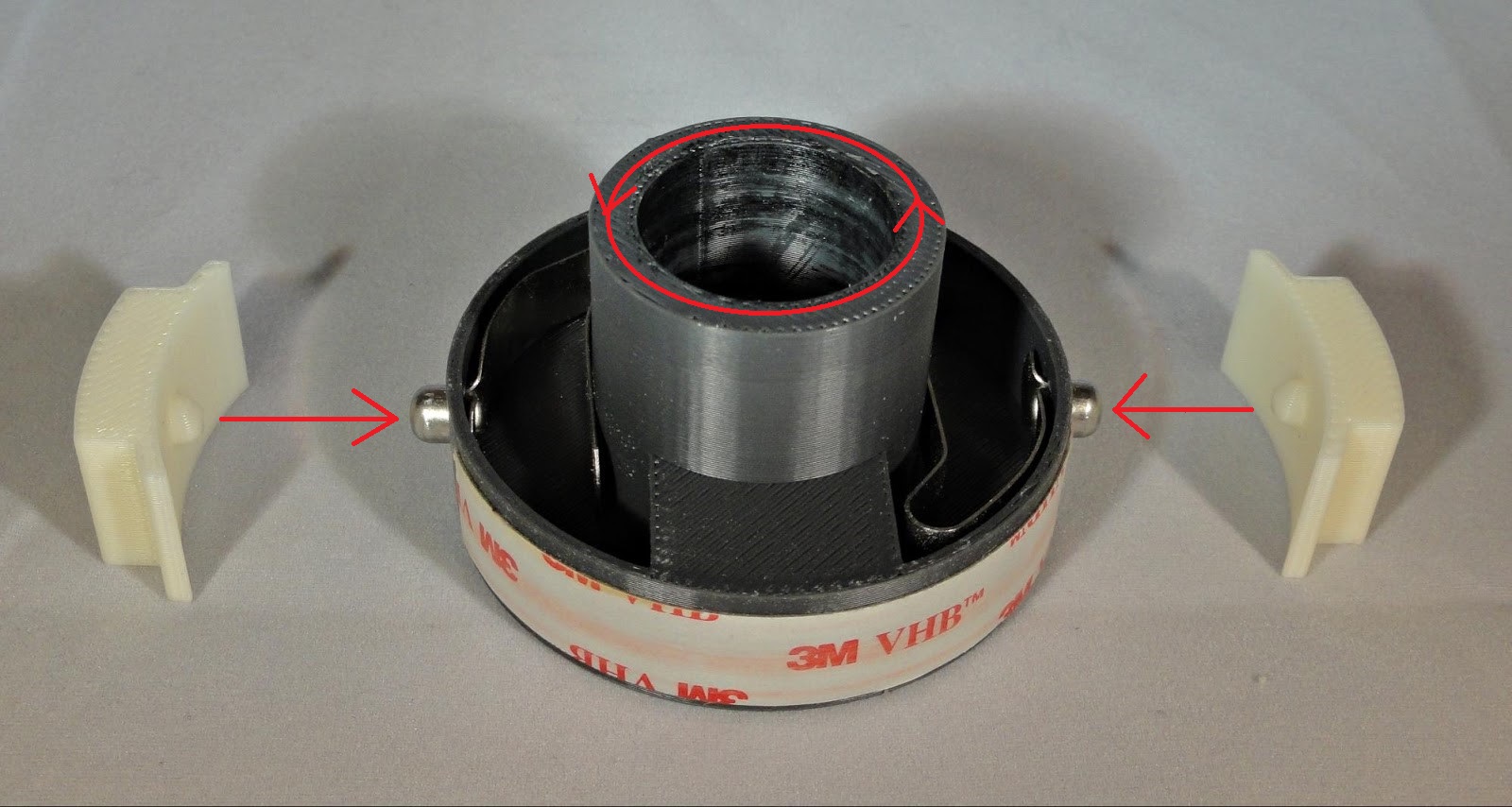
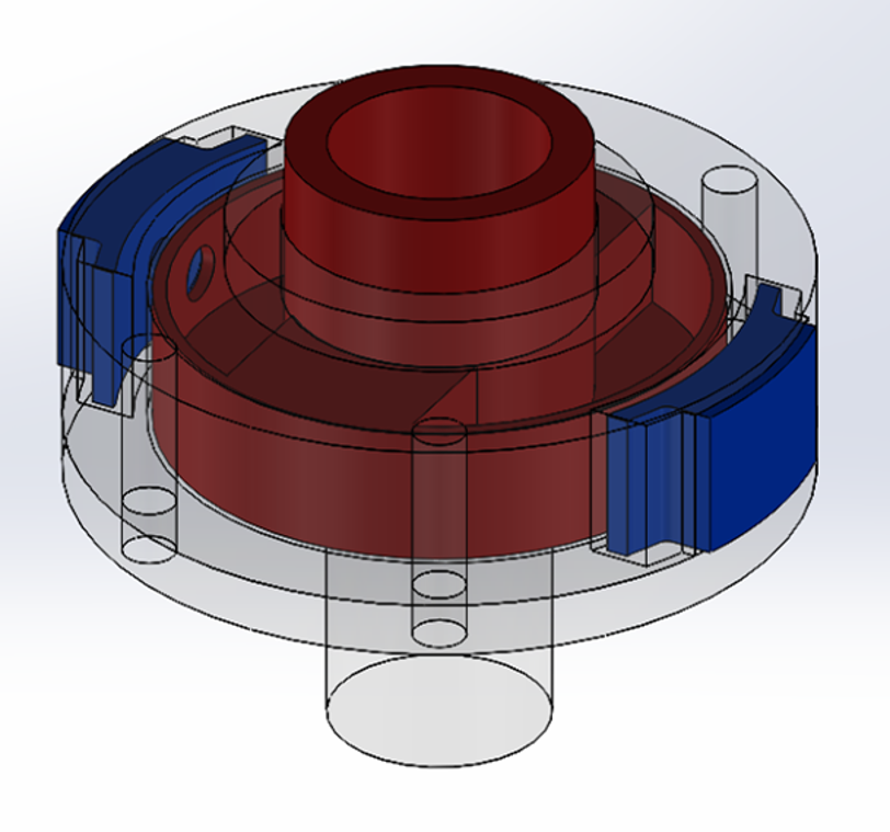
Having concluded the trip on a positive note, both organizations have expressed interest in seeing the prototype through to the next iteration and phase of testing. If all goes as planned, I will be returning to India in the summer with the new design and push the project into the production and manufacturing process. Below are some of the illustrated changes to the design. As before, the total number of parts (excluding fasteners) is 5, with only 3 moving parts.
Patent Pending